
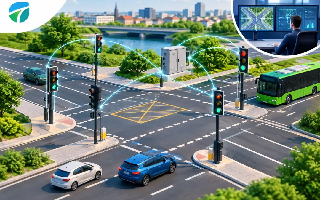
A detector can identify a waiting cyclist, an approaching vehicle or a growing queue with high accuracy, but that intelligence only improves traffic operation when the signal controller can use it correctly. This guide to Irish signal interfaces examines the practical layer between above-ground detection and traffic signal control – where sound specification prevents missed demands, unnecessary stage extensions and disruptive remedial works.
An Irish signal interface is not one universal connector or a simple add-on to the cabinet. It is the agreed method by which a detector communicates valid, configured and safe information to the controller. The right approach depends on the controller estate, the junction’s operational strategy, local authority requirements and the detection function being requested.
Guide to Irish Signal Interfaces: Define the Function First
Before choosing an interface, define exactly what the detector must achieve. A vehicle presence input used to place a demand has different timing, reliability and fault requirements from a radar input used for stage extension. Cycle detection may need to distinguish a rider waiting in a defined area from adjacent traffic, while queue detection may feed operational monitoring rather than directly alter signal timing.
This distinction matters because the controller responds to the interface, not to a detector’s raw data feed. The specification should state the required output condition, the detection zone, any delay or hold time, and what should happen when the detection system is unavailable. A clear functional description gives installers and signal engineers a testable basis for configuration.
For example, a side-road call may require a maintained presence output until the controller registers the demand. An extension input may need a pulse or an occupancy condition within a tightly defined approach zone. Treating both as simply a vehicle detected signal can cause inefficient operation, particularly at busy urban junctions where every unnecessary extension affects pedestrian waiting time and network capacity.
Match the Interface to the Controller Environment
The controller, not the detector, sets the practical boundary for integration. A site survey should establish the controller make and configuration, available input and output capacity, cabinet power arrangement, existing detection wiring, earthing provision, surge protection and the applicable approval process. It should also confirm whether the authority expects hard-wired inputs, a recognised communications interface or an intermediate input module.
Discrete inputs remain useful
Volt-free relay contacts and opto-isolated digital outputs are often appropriate where a clear detector state must be presented to a controller input. They are familiar to maintenance teams, straightforward to test and well suited to call, presence and extension functions. Their limitation is that they carry limited information: a contact confirms a configured condition, but it does not explain confidence, classification or the wider context behind it.
Where discrete outputs are selected, signal polarity, normally open or normally closed behaviour, pulse duration, input monitoring and fault state must be agreed. These details should never be left to assumptions during installation. A detector that fails safe by removing an output may be suitable for one function but cause undesirable repeated calls for another, depending on controller logic.
Communications interfaces need a defined purpose
Serial and IP-based interfaces can carry richer data, including lane-by-lane occupancy, classification, counts and detector health. They can reduce the number of physical interfaces where multiple detection zones are required. However, they introduce dependencies around protocol compatibility, network segregation, cyber security, data ownership and ongoing support.
A communications connection is justified when the controller or traffic management platform can make operational use of the additional data. It is not automatically preferable to a discrete input for a simple demand function. The most effective specification uses the least complex interface that fully meets the control objective while retaining a clear route for diagnostics and future expansion.
Keep safety functions in the right place
Detection can inform a signal controller, but it should not bypass the controller’s safety architecture. Intergreen periods, conflict monitoring, pedestrian clearance and other safety-critical decisions remain under approved controller logic and established signal design processes. The detector interface should provide dependable information, not create an uncontrolled path to alter signal states.
This is particularly relevant when replacing inductive loops. Above-ground radar and AI video detection can remove the need to cut the carriageway, but the change is more than a hardware swap. Loop inputs, detector channels and controller parameters may all need reviewing to make sure the new detection behaviour matches the junction’s intended operation.
A Practical Specification Process
Start with a site-specific operating problem. Is the objective to reduce side-road delay, detect cyclists more consistently, prevent wasteful green time, monitor queues or improve data quality? Define the outcome in operational terms before selecting equipment. A requirement such as detect all traffic is too broad; identify the approach, road users, speed range, detection area and response required.
Plan the detection and cabinet connection together
For radar, check mounting position, alignment, lane geometry and potential reflections from street furniture or large vehicles. For video detection, assess camera height, sight lines, lighting, occlusion and seasonal vegetation. The detector’s position determines whether its output can be trusted, and no interface choice will compensate for a poorly designed detection zone.
At the same time, plan the path into the signal cabinet. Confirm cable routes, gland capacity, termination space and electrical separation. Wireless sensors can reduce civil works, but their gateway, power supply, radio path and loss-of-communications behaviour still need to be engineered. Non-intrusive installation reduces carriageway disruption, not the need for disciplined integration.
Configure for actual traffic behaviour
A detection zone should reflect how road users approach and wait at the junction. A vehicle extension zone that is too long can hold a stage unnecessarily. One that is too short may miss slower-moving traffic. For cycle facilities, zone design must prevent adjacent motor traffic from generating false calls while still recognising riders in the intended waiting area.
Document detector settings alongside controller configuration. This includes zone names, output mapping, timing values, sensitivity settings and the intended fallback state. Clear records shorten fault finding and allow later changes to be made without reintroducing the original operational problem.
Prove performance before handover
Commissioning should test the complete chain, from the road user entering the detection area to the controller response and the displayed signal outcome. It should include representative traffic movements, not only a static check at the cabinet. Test vehicles at different speeds, cyclists where relevant, lane changes, queues and the edge conditions most likely to produce false or missed detection.
Commissioning and Whole-Life Assurance
A good test plan records both detections that must occur and detections that must not occur. It should verify demand registration, extension timing, stage cancellation where applicable, detector health indications and behaviour following power loss or communications loss. The signal engineer should be able to confirm that the controller handles every defined condition in accordance with the approved design.
Acceptance should also consider maintainability. Above-ground equipment provides a major advantage over road-embedded loops because detectors can often be accessed without carriageway excavation or extensive lane closures. That benefit is greatest when mounting brackets, cables, cabinet terminations and configuration records are all accessible and clearly labelled.
Remote diagnostics can support faster fault resolution, especially across dispersed networks, but they do not remove the need for periodic visual inspection. Camera lenses can become obscured, radar alignment can be affected by impact or mounting movement, and street-scene changes can alter a previously reliable detection field. A practical maintenance plan should identify these risks from the outset.
Better Interfaces Support Better Road Operation
The strongest case for above-ground detection is not simply that it avoids saw cuts in the road surface. It is that accurate, maintainable detection can give controllers better information with less disruption during installation and renewal. For authorities managing ageing loop assets, this can reduce roadworks exposure, protect carriageway condition and improve the evidence available for signal optimisation.
There are trade-offs. A simple contact interface may be easier to maintain but offer less diagnostic detail. A richer data connection may support network analysis but require more governance and integration work. The right answer depends on the junction, controller estate and intended use of the data.
For schemes across the Republic of Ireland, early collaboration between the detection supplier, signal designer, contractor and maintaining authority is the most reliable way to avoid late-stage interface changes. Specify the traffic outcome, prove the controller connection and retain the commissioning evidence. That is how an interface becomes a practical route to safer roads, reduced congestion and more sustainable traffic management.