
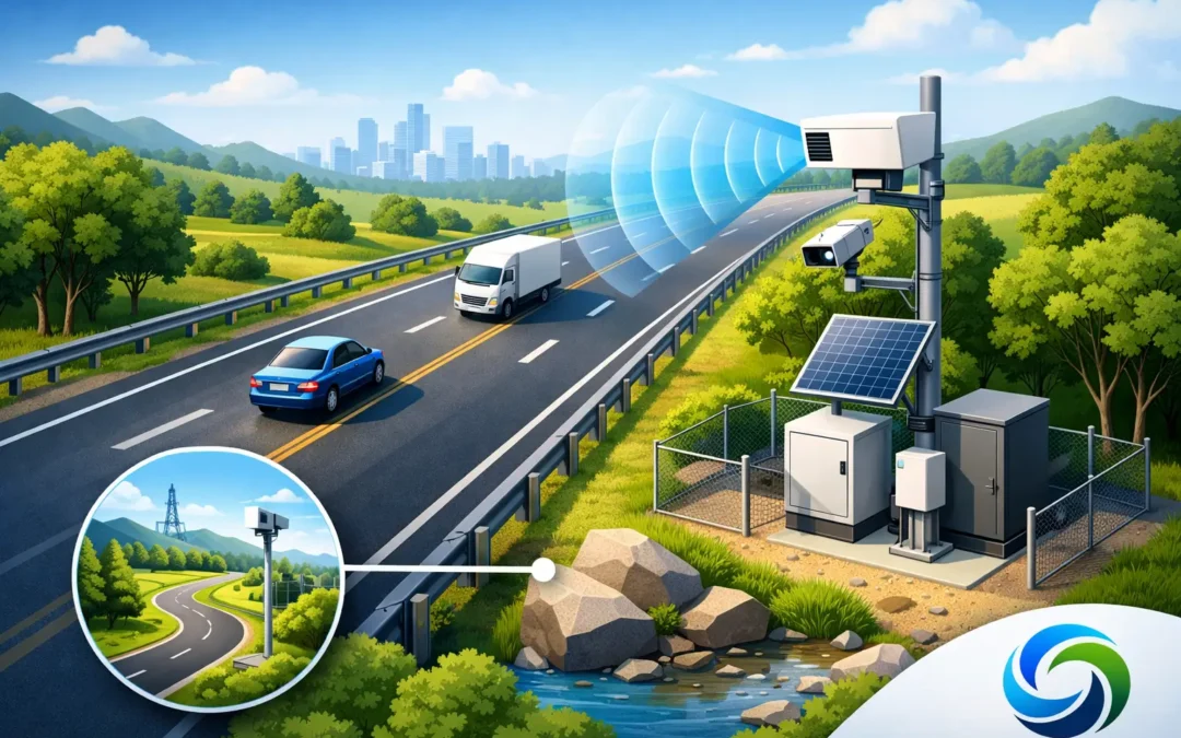
A radar detector can be specified correctly, commissioned correctly and still underperform because it is looking at the wrong piece of road. This guide to roadside radar siting is intended for highways teams, consultants and contractors who need dependable vehicle detection without the disruption, failure points and maintenance burden associated with road-embedded loops.
Roadside radar is not simply a replacement sensor. Its value lies in what it can observe from above ground: approaching vehicles, queue formation, speed, occupancy, direction of travel and, where the application requires it, cyclists. Achieving that value depends on a sightline that reflects the operational decision the detector is intended to support.
Start with the traffic decision, not the mounting point
The first siting question is not where a pole is available. It is what the system must know, and when it must know it. A detector used to extend a green phase needs a timely and stable approach presence signal. One supporting speed enforcement, a speed information display or a safety scheme may need accurate speed and direction over a defined measurement zone. Queue monitoring needs visibility of a longer road section and a clear definition of where a queue begins.
These objectives create different detection zones. A signal approach may require separate near-side and off-side lanes to be recognised at a defined distance from the stop line. A rural warning application may prioritise early detection of fast-moving vehicles. At a crossing, the priority may be reliable detection of cyclists and slower traffic close to the controlled area.
Document the operational requirement before a site visit: vehicle classes to be detected, lanes and movements of interest, required detection distance, speed range, output to the controller or platform, and the consequences of a missed or false detection. This prevents a common error: placing radar where it has a convenient field of view rather than where it can make the control strategy work.
Guide to roadside radar siting: establish a clear view
Radar needs a usable view of the target area, but a clear view is more than an unobstructed line from detector to carriageway. Survey the full scene in both directions of travel and consider what changes with the seasons, at peak periods and after future highway works.
Parked vehicles, loading activity, bus shelters, mature vegetation, street furniture and temporary works can all affect the effective detection area. On constrained urban streets, a large vehicle in the nearest lane may conceal traffic in the adjacent lane. On rural approaches, bends, crests and roadside banks can reduce the usable range well before the stated capability of the radar is reached.
The detector should normally be positioned so that its beam reaches the intended lanes without being dominated by traffic outside the area of interest. A wide viewing angle may appear attractive, but it can introduce unwanted detections from side roads, turning bays, adjacent carriageways or footway activity. Narrowing the monitored area through sensible positioning and configuration is often more effective than attempting to filter a poorly chosen view in software.
Height, offset and angle work together
Mounting height, lateral offset from the carriageway and radar angle must be considered as one geometry. Raising the detector can improve visibility across several lanes and reduce masking by nearer vehicles. However, excessive height or an unsuitable downward angle may make lane separation less distinct close to the detector or move the useful detection zone away from the required point.
A position too close to the kerb can create a shallow viewing angle across multiple lanes, increasing the chance that vehicles obscure one another. Moving the unit further back can improve the perspective, provided that roadside furniture, boundaries and cable routes permit it. Conversely, placing radar too far from the carriageway may weaken definition of the near lane or bring more non-target activity into view.
The optimum geometry depends on the detector model, the number and width of lanes, approach speed and the configured zone. Manufacturer installation guidance should set the permissible height and angle range. Site-specific adjustment should then be confirmed during commissioning with live traffic, not assumed from drawings alone.
Treat lane geometry as operational geometry
A lane plan is essential, particularly where the detector output influences signal operation. Mark the detection zones against the actual lane markings, stop line, turn pockets, cycle facilities, bus lanes and refuge islands. Then assess how traffic behaves rather than how the layout was intended to behave.
For example, vehicles may straddle lanes on a narrow approach, use a hatched area to reach a turning lane, or queue beyond the formal lane boundary. At junctions with permitted turns, a radar zone that includes vehicles waiting for a gap can extend demand unnecessarily. A zone that is too short may fail to hold a phase for an HGV or a cycle moving slowly through the approach.
Where lane-by-lane information is required, validate that adjacent streams can be distinguished under dense traffic. This is especially relevant on multi-lane approaches, high-speed routes and locations with a high proportion of lorries. A single broad detection area can be appropriate for some demand-responsive applications, but it is not a substitute for lane-specific logic where the controller needs it.
Account for the road environment
Roadside radar siting must reflect the physical environment and the likelihood of change. A detector that performs well on an empty commissioning day may face very different conditions during school pick-up, seasonal tourism, market days or diversionary traffic.
At signalised junctions, examine opposing approach traffic, turning movements and any parallel carriageway. Radar can identify direction of travel, but the detector must be oriented and configured to prevent irrelevant movements influencing the output. On dual carriageways, the central reserve, vehicle barriers and opposing traffic should all be considered when selecting a mounting location.
Curved roads require particular care. Radar may still be suitable, but the measurable area needs to follow a section of carriageway that remains visible and within the detector’s intended angular range. On a crest, position the detector to see vehicles early enough for the application while avoiding a detection gap immediately behind the summit.
Weather rarely prevents radar from being a practical above-ground detection option, but site conditions still matter. Standing water, spray, snow accumulation, severe winds affecting supporting structures and vegetation movement should be examined as part of the survey. The aim is not to find a theoretically perfect location. It is to select one that remains dependable through normal operating conditions.
Design the installation for safe access and long-term service
Non-intrusive detection removes the need to cut the carriageway, which can reduce traffic management requirements and avoid loop failures caused by resurfacing or road movement. That advantage is diminished if the detector is mounted where access is difficult, unsafe or dependent on repeated lane closures.
Use an existing signal pole, lighting column or dedicated support only where its location, structural suitability and available height meet the detection need. Do not compromise the detection geometry simply to avoid a new mounting arrangement. Equally, do not create a maintenance problem by selecting a position with no safe access route or with excessive exposure to impact risk.
Power, communications and integration should be reviewed early. A radar can provide valuable data, but the installation must support the intended connection to the signal controller, speed display, traffic counter or data platform. Allow for cabinet space, cable protection, wireless coverage where applicable, earthing requirements and the inspection arrangements expected by the asset owner.
Commission against real traffic, then verify the outcome
Commissioning is where the site design becomes an operating system. Set the zones, direction filters, speed thresholds and output logic against the agreed purpose. Observe free-flow and queued traffic, different vehicle types, turning movements and, where relevant, cyclists. If the site is busy, a short observation period is rarely enough to expose all edge cases.
Validation should compare detector outputs with what is visibly happening on the road. For a signal application, check that calls occur when expected, that demand is not held by irrelevant traffic, and that no material gaps appear in the approach detection area. For monitoring applications, compare recorded volumes, classifications and speeds against manual observations or an agreed reference method.
Keep a commissioning record that includes photographs of the installed view, mounting height, orientation, configured zones, firmware details, controller inputs and test results. This evidence is valuable when road markings change, vegetation grows, a collision damages street furniture or operational teams query a change in performance.
When one radar position is not enough
Some sites demand more than a single detector. Complex junctions, long approaches, multi-lane high-speed roads and locations with significant masking may need separate views or complementary technologies. A second radar can improve coverage where a primary view is blocked, while AI video detection may be the better choice where detailed classification, pedestrian presence or complex movement analysis is required.
The decision should be based on the control and safety requirement, not an assumption that one technology solves every detection problem. C & T Technology’s approach is to match above-ground detection to the application so that installation speed is balanced with reliable, actionable data.
A well-sited radar becomes part of the road network’s decision-making infrastructure. Survey the real traffic behaviour, define the required detection outcome and verify performance after commissioning. Those three disciplines will do more for safer roads, reduced congestion and maintainable assets than any nominal detector range on a datasheet.