
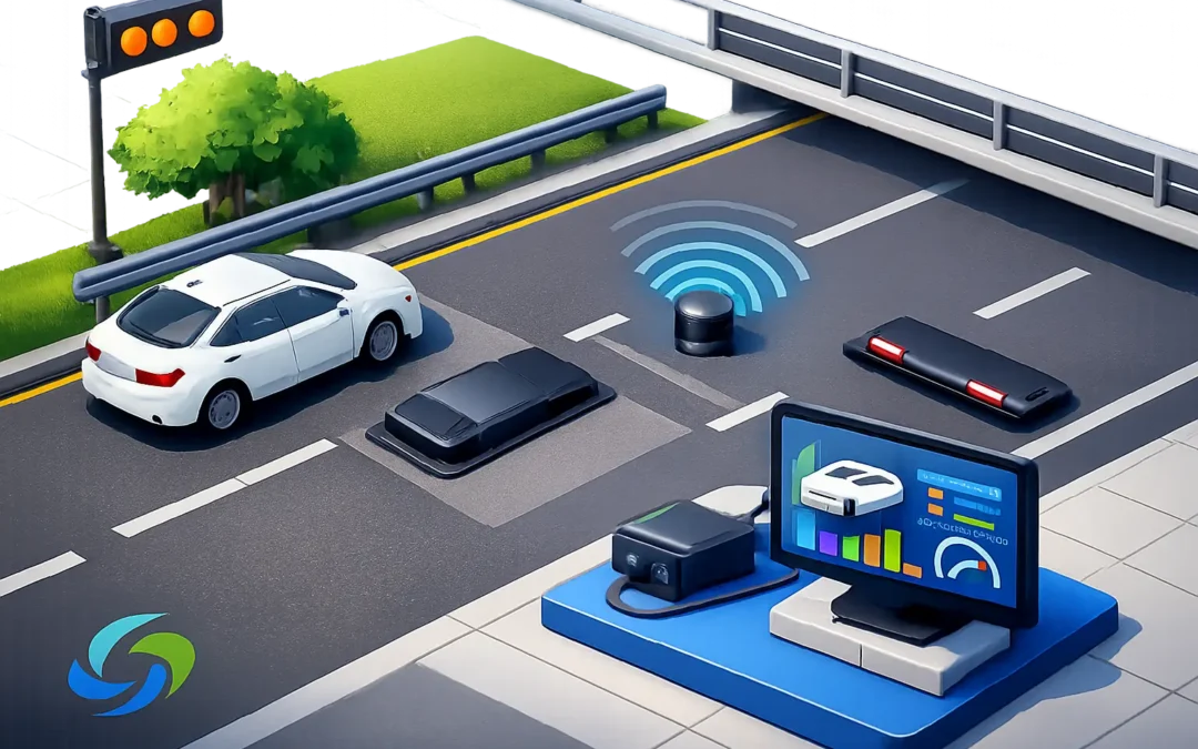
A detector installation can be technically correct yet operationally poor if the sensor is aimed at the wrong detection zone, mounted on an unstable pole, or configured without reference to the junction strategy. Knowing how to install above ground traffic sensors therefore means more than fixing hardware to street furniture. It is a controlled process of survey, safe installation, field of view design, configuration and validation against real traffic movements.
Above-ground radar, AI video and wireless detection technologies remove the need to cut carriageways for inductive loops. That reduces traffic management requirements, avoids reinstatement risk and makes future changes easier. The trade-off is that installation quality becomes central to detection performance. A clear mounting position, sound cabling practice and disciplined commissioning are what turn a capable sensor into useful signal-control or traffic-data infrastructure.
Start with the operational requirement
Before selecting a mounting position, define what the sensor must achieve. A stop-line presence detector for a traffic signal approach has different requirements from a system measuring approach speed, queue length, cycle lane occupancy or vehicle classification. The detection objective determines the technology, field of view, mounting height, processing rules and interface to the controller or data platform.
For signal control, establish the required call points, extension zones and any demand-dependent logic. For safety schemes, identify the road users to be detected, including cyclists, pedestrians, motorcycles and larger vehicles where relevant. For monitoring applications, agree the data outputs, aggregation interval and accuracy expectations before installation begins.
This stage should also account for the local environment. Junction geometry, lane markings, gradients, turning movements, street trees, bus stops, parked vehicles and adjacent signals can all affect what a sensor sees. A site that works well for radar may present challenges for video analytics due to glare, low sun or frequent occlusion. There is no single best technology for every location.
Complete a proper site survey
A site survey should confirm the practical constraints rather than rely solely on drawings. Measure the detection area, note vehicle paths and identify suitable poles, gantries or dedicated posts. Check that the proposed structure is sufficiently rigid, has a clear view of the required zone and can support the sensor without vibration or excessive movement in wind.
For camera-based detection, survey sightlines in both daylight and reduced-light conditions where possible. Consider seasonal changes too. Foliage that is not an issue in winter can obstruct a camera in summer. Assess potential sources of glare, headlamp flare, reflective signs and shadows from buildings.
Radar is less affected by weather and lighting, but it still needs a controlled detection area. Its orientation should minimise detection of unwanted adjacent lanes, footways, side roads or moving objects beyond the intended approach. At complex junctions, the sensor location may need to balance coverage against the risk of cross-traffic being interpreted as a valid demand.
The survey should also identify electrical supply, communications routes, controller cabinet capacity and earthing arrangements. If existing infrastructure is being reused, verify its condition rather than assume the available cable, pole or cabinet terminals are suitable.
Plan installation around safe access and traffic management
Above-ground equipment eliminates carriageway cutting, but it does not eliminate site risk. Prepare a method statement and risk assessment that covers work at height, live traffic, electrical isolation, cable routes and lane or footway management. Coordinate with the highway authority, signal maintenance contractor and network operator where access or approvals are required.
Programme the work around the least disruptive access window. A well-planned installation may be completed from a footway or verge with limited traffic management. Other locations, particularly on high-speed roads or constrained urban junctions, may require lane closures and specialist access equipment.
Confirm that the installation team has the current drawings, detector configuration plan, mounting brackets, correct connectors, weatherproof glands and test equipment before arriving on site. Delays commonly arise from small omissions, such as an unsuitable pole clamp or a missing interface cable, rather than the sensor itself.
Mount and wire the sensor correctly
Mount the unit at the manufacturer-approved height and angle for the application. Do not treat these values as generic recommendations. Mounting height affects the usable field of view, target separation and accuracy of calculated positions. Tilt and azimuth affect where the sensor looks and whether it captures the intended lanes without creating false detections.
Use brackets designed for the pole diameter and sensor weight. Tighten fixings to the specified torque and ensure the final assembly cannot rotate or slip. Avoid positions where routine vibration, passing heavy goods vehicles or repeated pole movement will alter alignment over time.
Route cables neatly, protect them from sharp edges and maintain suitable drip loops before enclosures and glands. External connections must be appropriately rated for the environment, with sealing and strain relief completed carefully. Water ingress and damaged cable sheaths are avoidable causes of intermittent faults.
At the controller end, label every termination clearly. Connect power, communications and input or output interfaces in accordance with the approved wiring schedule. Depending on the solution, this may include relay outputs, digital I/O, Ethernet, serial communications or a wireless gateway. Keep detector cabling segregated from sources of electrical interference where the installation design requires it.
Configure detection zones for the real road layout
The physical installation is only half the job. Configure zones using the live scene, not merely a plan view. For video detection, map lanes, stop lines, approaches and exclusion areas accurately within the image. For radar, set the relevant detection ranges, lane boundaries, direction filters, classification rules and sensitivity parameters.
Each zone should correspond to a defined operational purpose. A presence zone near the stop line should not be so broad that it includes vehicles waiting in an adjacent lane. An advance extension zone should provide sufficient time for the controller logic without being triggered by unrelated movements. Cycle detection needs particular care where cyclists share space with general traffic or approach at lower speeds.
Avoid compensating for a poor mounting position with overly broad software zones. This often produces false calls and makes faults harder to diagnose. If the scene cannot be configured cleanly, revisit the sensor position or orientation.
Validate before commissioning
Validation must prove that the system meets its intended function under live conditions. Start with a physical check: confirm the sensor is secure, sealed, correctly aligned and free from obstructions. Then verify power, communications, device status and interface signals.
Test each detection zone with representative road users and movements. This should include cars, vans, buses, lorries, bicycles and pedestrians where they form part of the specification. Observe both successful detections and potential false targets, such as vehicles in neighbouring lanes, turning traffic, street furniture or pedestrians waiting near the kerb.
For traffic signal applications, confirm that detector outputs are received by the controller and produce the expected stage demand, extension or cancellation behaviour. Check the effect on existing intergreens, pedestrian stages and linked junction operation. A detector should improve the control strategy, not introduce unexplained calls that reduce capacity elsewhere.
Capture commissioning evidence, including final photographs, mounting details, configuration files, zone diagrams, cable test results and functional test records. This documentation supports future maintenance and gives the asset owner a clear baseline if traffic patterns or signal plans change.
Maintain performance after handover
Above-ground traffic sensors generally reduce the maintenance burden associated with failed loops and carriageway reinstatement, but they still require planned inspection. Review detection logs and controller fault records after the first weeks of operation. Early operational data can reveal a zone that is too sensitive, a lane assignment that needs refinement or a view beginning to be obscured.
Schedule periodic checks for contamination on optical surfaces, vegetation growth, accidental pole impacts, loose fixings and changes to signs or road markings. Any alteration to the junction layout should trigger a review of detector settings. A new cycle facility, bus stop relocation or revised lane discipline can materially change detection performance.
For authorities and contractors across the UK and Ireland, the practical advantage is clear: above-ground detection can be installed and adapted without repeatedly excavating the road. The best results come from treating installation as part of the traffic engineering solution, with the sensor, controller logic and road environment configured to work together. When that discipline is applied, detection becomes a reliable foundation for safer roads, reduced congestion and better network decisions.